Basic design process

I'm using Fusion 360, other tools are left as an exercise...

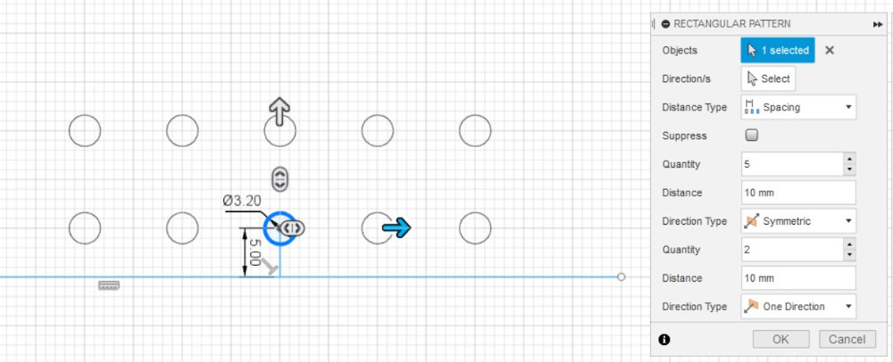
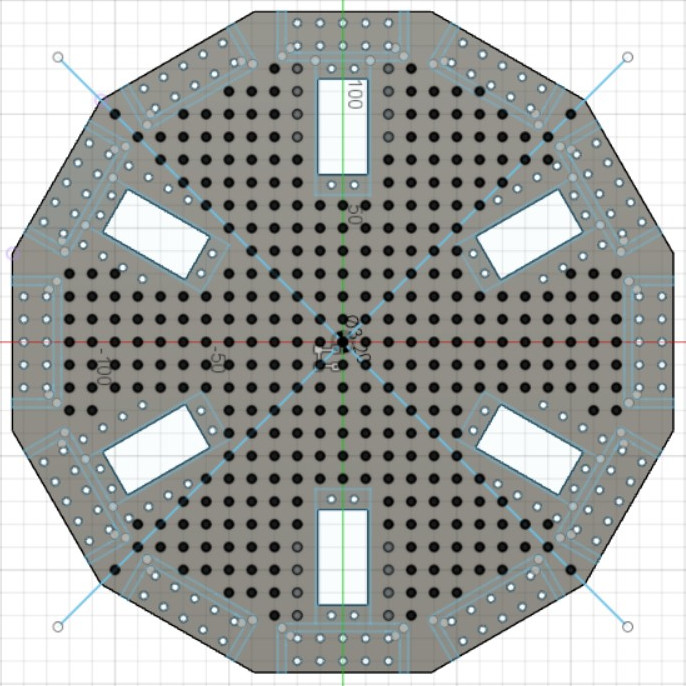
Holes are 3.2mm in a 1 cm grid, centered at the center of the disk, and
extending through to edges 12,3,6,9, which helps keep everything stackable.

The edge pattern is 2 deep for strength. Most are 2x5 or 2x3.
A 90mm disk only has room for 2x1.

The holes along the side of the cutouts continue the edge pattern,
and allow for more rigid mounting of adapters, manipulators, etc.

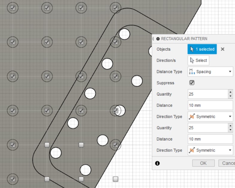
pattern suppression and edge definition

Sketch 1 On the X,Y plane; centered at 0,0;
create a 12 sided circumscribed polygon.
Extrude 1 To material thickness
Sketch 2 Make one edge pattern,
a 3.2mm hole centered 5mm from the edge,
rectangular pattern of holes, 2x1 or 2x3 or 2x5.
Create a circular pattern of 12 of those edge patterns.
Extrude 2 Cut thru all those holes
Sketch 3

Make one cutout pattern,
with rectangular pattern for the surrounding holes.

Holes that are over air will cause Tool Body warnings
in the extrude step, so check the suppress box, and
uncheck any conflicts or extras.

Replicate the cutout with a circular pattern of 12,
use suppress to get desired layout.

Extrude 3 Cut thru all those new features
Sketch 4

Put a 3.2mm hole in the center, make a rectangular pattern
to cover the whole disk, symmetrical X & Y, with suppress.
The grid pattern should be aligned to overlap the edge patterns
at 12,3,6,9. Uncheck anything that overlaps edges or cutouts.

Extrude 4 Cut thru new holes
Save Save as Mesh (STL)

in/petecarpenter - updated 2023-10-10